Inverted Pendulum Control System
Project Information
- Category: Lab Project
- Technologies: MATLAB, Simulink
- Location: University of Kent
- Date: 2024
About the Project
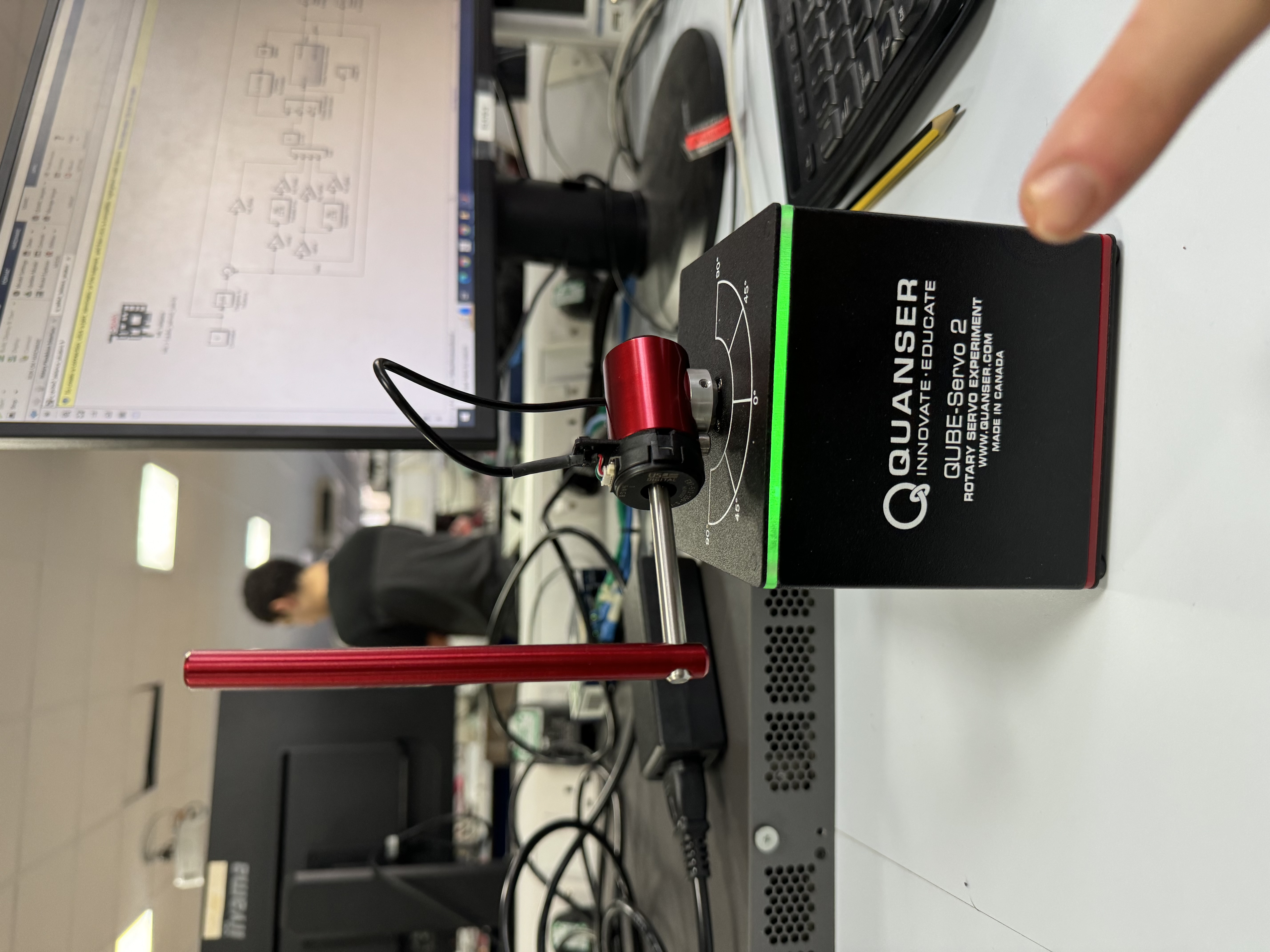
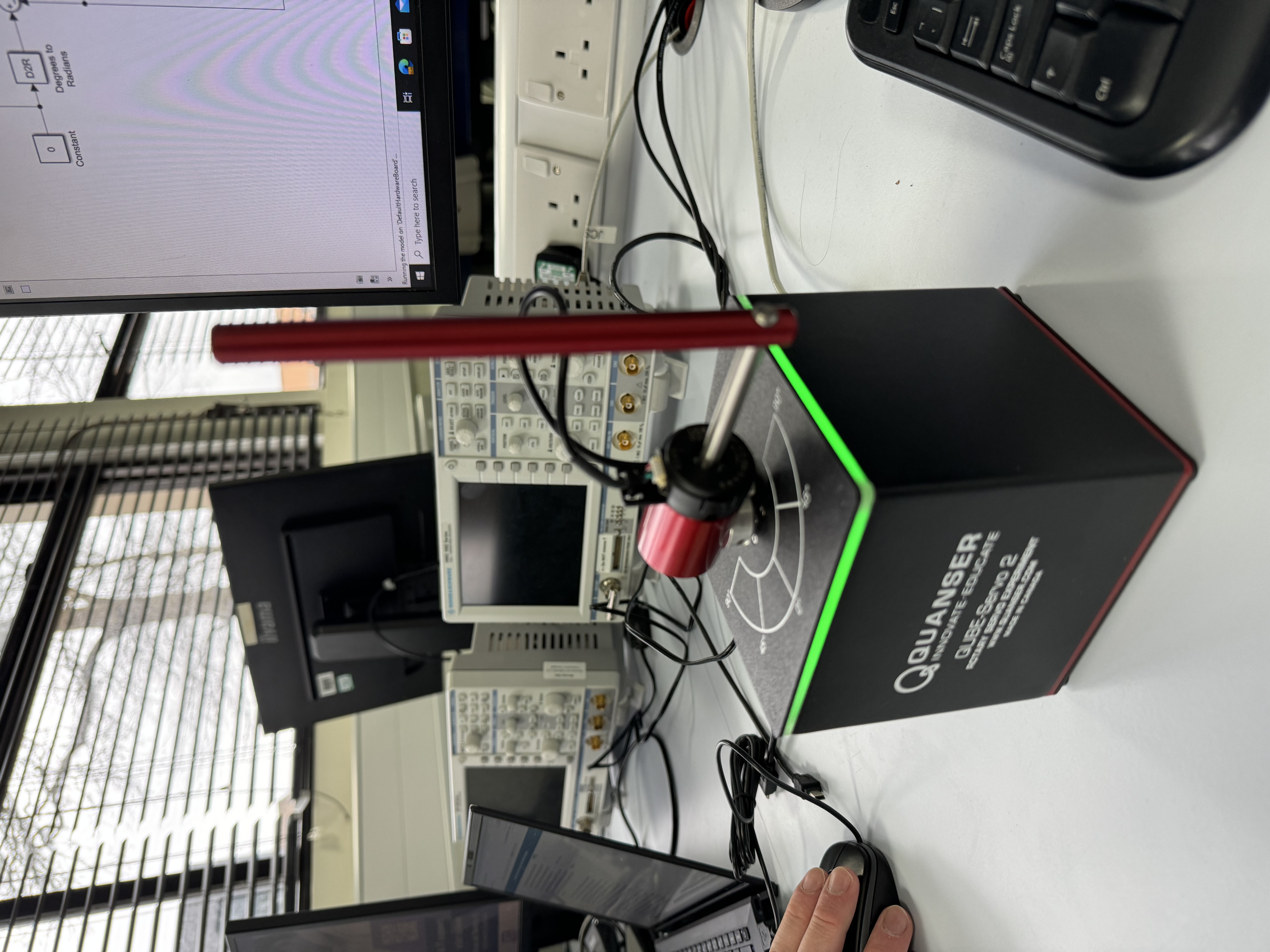
The inverted pendulum is a classic problem in dynamics and control theory, often used to demonstrate the principles of feedback control systems. During a series of university lab sessions, I worked on setting up and controlling an inverted pendulum using a DC motor, Simulink, and PID control principles. The project provided a comprehensive learning experience, from the foundational understanding of energy transfer to the practical application of control algorithms.
Project Background
The inverted pendulum system is inherently unstable, making it an excellent case study for learning about control systems. The goal of these lab sessions was to develop a system that could maintain the pendulum in an upright position by controlling the angle of a DC motor attached to the base. The challenge lay in understanding the physical dynamics of the pendulum, modeling these dynamics mathematically, and then applying a control strategy to stabilize the system.
Mechanical, Electrical Integration, and Control Implementation
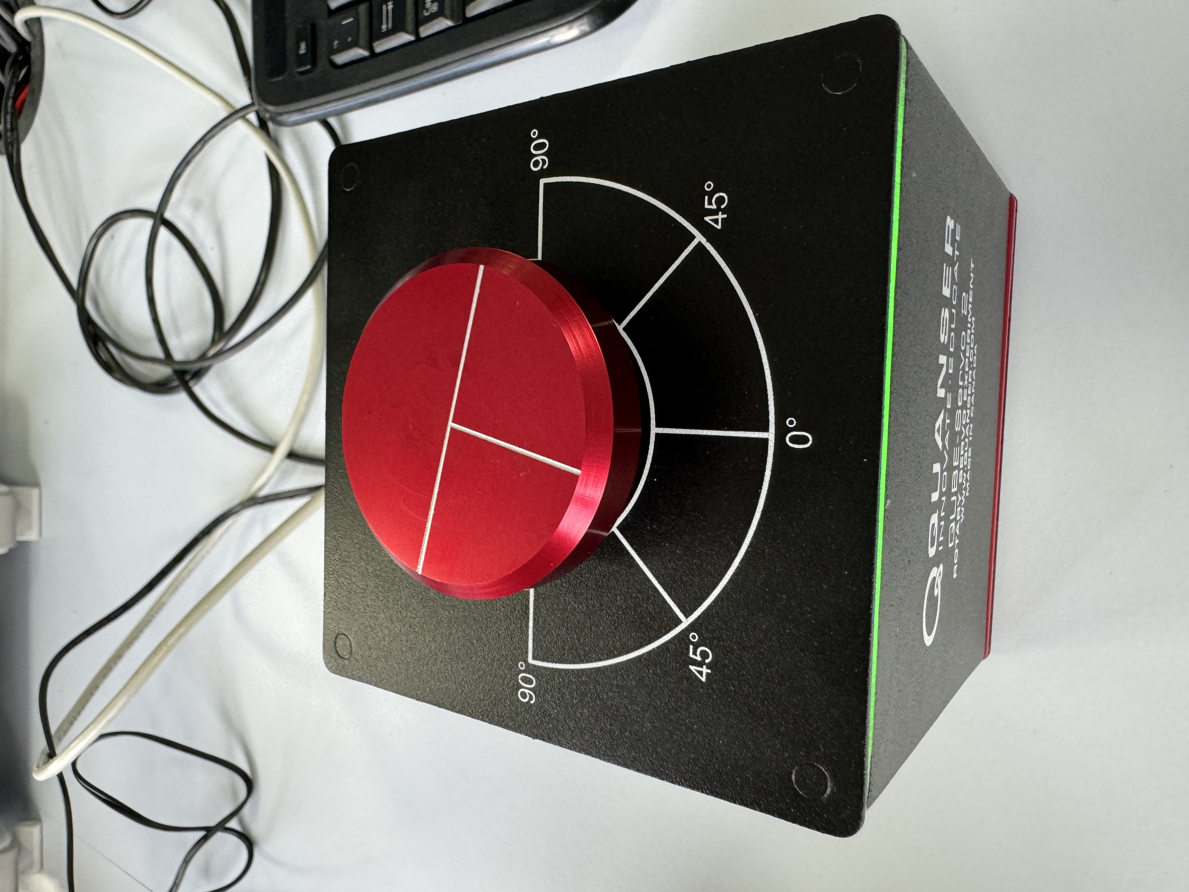
As part of the lab work, we started by exploring the mechanical aspects of the system, focusing on how mechanical energy could be harnessed and controlled using electrical inputs. The DC motor played a crucial role in this process, converting electrical energy into the mechanical motion required to adjust the pendulum's angle. Understanding this energy conversion was fundamental to designing the control system.
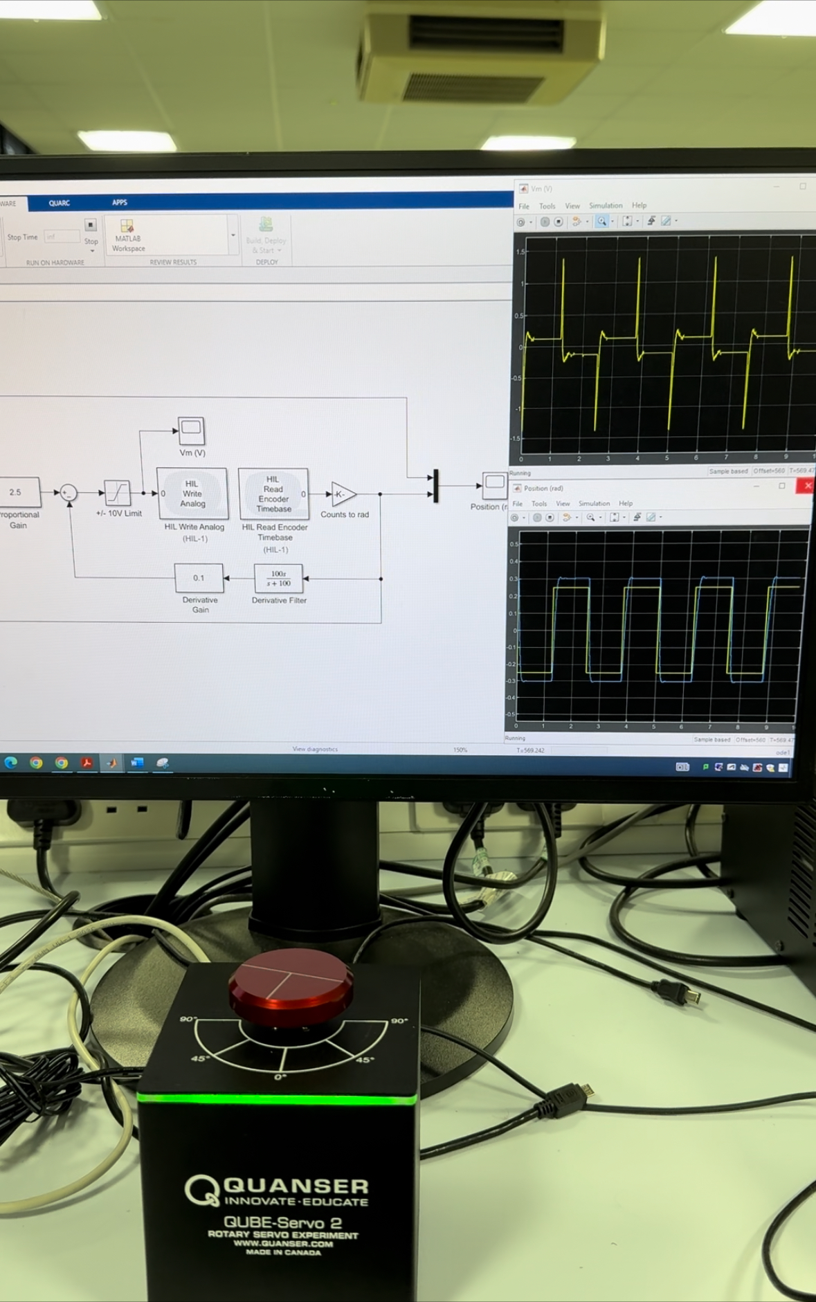
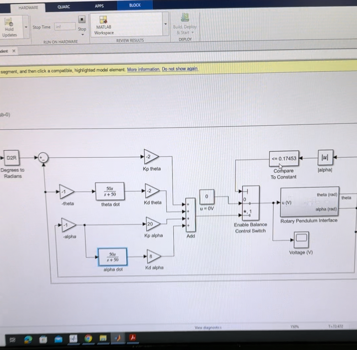
To predict and control the pendulum's behavior, we modeled the system using differential equations that described the relationship between the pendulum's motion and the forces acting on it, including gravity and the motor's torque. Using this model, we employed Simulink software to implement a control system that successfully controlled the pendulum in the real world.
PID Control Implementation
The heart of the control system was the PID (Proportional-Integral-Derivative) controller. This controller was tasked with adjusting the motor's output to keep the pendulum balanced. By fine-tuning the PID parameters, we were able to achieve the precise control necessary to maintain stability. The process of designing and tuning the PID controller was iterative, requiring careful observation and adjustment to ensure optimal performance.
Final Integration and Testing
With the control system in place, we moved on to the practical challenge of balancing the inverted pendulum. This involved connecting the DC motor to a computer and using real-time feedback from sensors to adjust the motor's angle. The success of this stage was a testament to the accuracy of our model and the effectiveness of the PID control strategy. The system's ability to keep the pendulum upright demonstrated the power of combining theoretical knowledge with practical engineering skills.
Key Learnings and Outcomes
This series of lab sessions was a significant milestone in my understanding of control systems and their practical applications. It highlighted the importance of modeling in engineering design, as well as the critical role of feedback in maintaining system stability. Moreover, working on the inverted pendulum sparked an interest in control theory and its applications in robotics and automation.
Gallery
Welcome to the gallery! This collection showcases the various stages of development and challenges we encountered.

